HomeLab, Networking, Cables... let's look at the requirements for building custom keystone jacks and RS232 serial cables. A minor discussion of the core components is necessary before looking at the technical aspects.
This post was written over a series of months, initially as lab notes, with some bits and bytes added each time the tools come out or the patch panels are rewired. While perhaps not a common task, hopefully the knowledge finds someone else looking for these solutions.
Switch-Port System Roles
This post discusses several types of connections and signals conversion in a field where the list of potential operating modes is prone to complexity. Brands involve APC, Avocent, Blackbox, Cisco, Cyclades, Moxa, Netshelter, OpenGear, Vertiv, and more - but here in my HomeLab and in the enterprises in which I've worked, there's a common requirement for critical equipment to talk to a System Infrastructure Manager system or OOB device.
System Infrastructure Manager
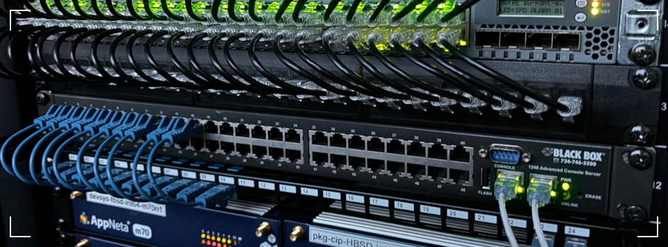
Featured in the post's header image, I'm using Blackbox for OOB services, but these specs are matched by various brands in similar price points.
Device: BlackBox model LES1248a out‑of‑band (OOB) connection manager
Specs: 48‑port, 1U, dual-PSU, dual-LAN, cellular 3G and POTS optional
Provided Features
- Remote access services using web-based serial console interface for infrastructure devices (switches, routers, PDUs, UPS, etc).
- Centralizes remote‑management via multi-protocol connections and bridging between serial devices and user-facing network services.
- Access‑control lists (ACLs) and role‑based access control (RBAC)
- Monitoring, logging, and alerting
Reference: Generic Pin Mapping for 8P8C RJ45
This represents the usual 8P8C RJ45 connector layout, with pin usage according to different serial standards. While we are focused on RS232, it can be helpful for visualization purposes to see how other standards are implemented.
| Pinout | EIA‑232 | EIA‑422 | EIA‑485 Full Duplex | EIA‑485 Half Duplex |
|---|---|---|---|---|
| 1 (in) | DCD | |||
| 2 (out) | RTS | TxD+ | TxD | DATA+ |
| 3 (in) | DSR | |||
| 4 (out) | TxD | TxD‑ | TxD‑ | DATA‑ |
| 5 (in) | RxD | RxD+ | RxD+ | |
| 6 | GND | GND | GND | GND |
| 7 (in) | CTS | RxD‑ | RxD‑ | |
| 8 (out) | DTR |
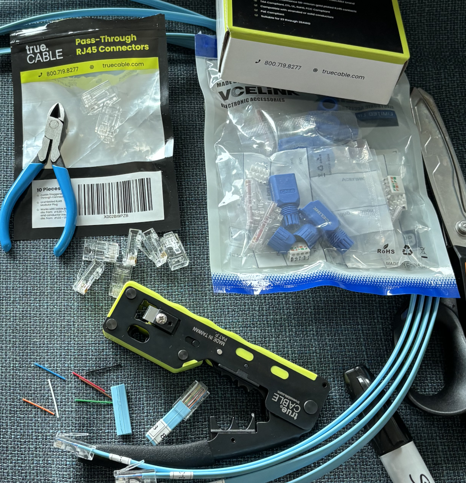
Working with Keystone Connectors
Those 48 ports aren't going to fill themselves up without some occasional head scratching along the lines of..
Q: "How can I connect this RJ12 RS232 based APC PDU to a RJ45 RS232 infrastructure manager?"
A: You're going to have to convert the pin-out for an RJ12 cable to the expected pin-map of an RJ45 RS232 rollover cable.
Great. I have those requirements!
Let's see the various pin and cable maps involved with some common use cases. We'll get to the RJ12 content, but let's see standard mappings first.
1) Standard Ethernet, 8P8C Straight-Straight
These are simple and have no pin conversion to map. This is a basic reference only, there's nothing to do.
| J1 (Keystone Front) | J2 (Keystone Back) |
|---|---|
| J1‑1 → | J2‑1 |
| J1‑2 → | J2‑2 |
| J1‑3 → | J2‑3 |
| J1‑4 → | J2‑4 |
| J1‑5 → | J2‑5 |
| J1‑6 → | J2‑6 |
| J1‑7 → | J2‑7 |
| J1‑8 → | J2-8 |
2) Cisco Rollover, 8P8C Switch-Crossover
Standard rollover cable pin-map. In this case it's what we want to use when connecting a Cisco style switch to our Blackbox (both with RJ45 RS232 ports).
| Pin | Signal | Direction |
|---|---|---|
| 1 | DCD | in |
| 2 | RTS | out |
| 3 | DSR | in |
| 4 | TxD | out |
| 5 | RxD | in |
| 6 | GND | (none) |
| 7 | CTS | in |
| 8 | DTR | out |
Keystone Pins, 8P8C Switch-Crossover
My patch panels use keystone jacks to simplify things, and they ship with straight-through RJ45-RJ45 connectors which do not change the wiring. That's fine in some cases, but let's see what we need to do to build a custom crossover keystone jack.
| J1 (BlackBox side) | J2 (Cisco side) |
|---|---|
| J1‑2 (RTS) → | J2‑8 (CTS) |
| J1‑3 (DSR) → | J2‑2 (DTR) (optional) |
| J1‑4 (TxD) → | J2‑6 (RxD) |
| J1‑5 (RxD) → | J2‑3 (TxD) |
| J1‑6 (GND) → | J2‑4 (GND) |
| J1‑7 (CTS) → | J2‑1 (RTS) |
| J1‑8 (DTR) → | J2‑7 (DSR) |
| J1‑1 (DCD) → | — (no connection to J2) |
3) APC PDU Conversion, 6P6C RJ12 → 8P8C RJ45
- APC PDU side: 6P6C RJ12 connector with grey ethernet cable
- Blackbox side: 8P8C RJ45 connector with grey ethernet cable
RJ12 6P6C Connector for APC (940-0144A)
While APC has more than one RJ12 connector on their products, this one is the most common from my SKU usage in the enterprise.
| Pin | Signal | Direction / Notes |
|---|---|---|
| 1 | — | No connection (NC) |
| 2 | GND | Ground |
| 3 | TX | Serial transmit to peer |
| 4 | RX | Serial receive from peer |
| 5 | GND | Ground |
| 6 | — | No connection (NC) |
Keystone Pins, 6P6C RJ12 for APC PDU
This is where things get fun? We have an 8-pin cable on both sides of the jack, but only 4 pins are needed on the APC RJ12 side. Look closely and plan ahead when you're chopping wires and punching connectors.
Rj45 Blackbox View
| J1 (BlackBox side) | J2 (APC side) |
|---|---|
| J1‑1 (DCD) | — (no connection to J2) |
| J1‑2 | — (no connection to J2) |
| J1‑3 | — (no connection to J2) |
| J1‑4 (TxD – out) | J2‑4 (RxD – input to APC) |
| J1‑5 (RxD – in) | J2‑3 (TxD – output of APC) |
| J1‑6 (GND) | J2‑2 (GND) and J2‑5 (GND) |
| J1‑7 | — (no connection to J2) |
| J1‑8 | — (no connection to J2) |
Rj12 APC View
| APC RJ12 (6P6C) | Console RJ45 (8P8C) |
|---|---|
| pin 1 – | – |
| pin 2 GND | pin 4 GND |
| pin 3 TX → | pin 6 RXD (into console) |
| pin 4 RX ← | pin 3 TXD (out of console) |
| pin 5 GND | pin 5 GND (optional second ground) |
| pin 6 – | – |
USOC (RJ‑12) Pinout
| Pin (L→R) | Colour (typical US C) | Pair |
|---|---|---|
| 1 | White | P3 |
| 2 | Black | P2 |
| 3 | Red | P1 |
| 4 | Green | P1 |
| 5 | Yellow | P2 |
| 6 | Blue | P3 |
RJ‑45 (T568B) Pinout
| Pin (L→R) | Colour (T568B) |
|---|---|
| 1 | White‑Orange |
| 2 | Orange |
| 3 | White‑Green |
| 4 | Blue |
| 5 | White‑Blue |
| 6 | Green |
| 7 | White‑Brown |
| 8 | Brown |
Both USOC/T568B tables assume the connector tab is facing down and the pins are read left‑to‑right.
Regarding Flow Control - DSR/DTR Assertion
Fun times with RS232 sometimes involve flow-control, though often this is set to "None", there are more options than None where None is concerned. Let's see why Blackbox offers the following options, given the following debugging scenario:
Defining a Common Flow Control Issue
Problem: Blackbox shows incomplete port status*, with no terminal output when connecting via Cisco rollover cable.
[*] ("RTS | DTR" instead of "RTS | DSR | DTR | DCD")
Signal Debugging Workflow
| Configuration | Action | Purpose |
|---|---|---|
| 1. Validate "Hardware Flow Control" | Enable sampling | Detect carrier signals |
| 2. Pinout Verification | Check mappings | Ensure proper signal visibility |
| 3. Signal Testing | Use multimeter | Confirm remote device asserts DSR/DCD |
| 4. Manual Carrier Assert | Add loop adapter | Force carrier presence |
Inspecting Flow Control Modes
| Configuration | Result |
|---|---|
| None - Default | Take no action |
| None - Flow control signals unpowered | FC signal pins explicitly disabled |
| Hardware | (implied: signals are powered) |
| Software | (implied: signals are powered) |
| Software - Flow control signals unpowered | FC signal pins explicitly disabled |
- Q: What, surely the two None types are equivalent?
- A: They are not equivalent.
The port is usable in either "None-Type" modality only if TxD/RxD signals are present. The console server will report "No signal data available" when the connected Blackbox port is operating in the following states:
- not powering when it needs power
- actively sampling modem-control lines
- when the remote device side never asserts them
Confusions with State-Mode Usability
Using "None - Flow control signals unpowered" disables the port's modem-line sensing, which prevents the appliance from reporting DSR/DCD/CTS.
- Whether or not you can connect over the line depends whether the device has active TxD/RxD connection signals, irrespective of whether Blackbox knows about DSR/DCD/CTS state.
- Alternatively, the remote device may never assert DSR/DCD, as many network-console ports don't provide carrier signals, so the server has nothing to report.
Ok... What else?
Despite many efforts and assumptions, it's a fact that RS232 is not going anywhere any time soon and it remains not simply useful but necessary.
The global view of serial connection usage includes datacenters, industrial automation systems, expansive cellular / broadband / telco networking hardware, mainframe connected terminals, all the way to a near-endless number of embedded systems. Good times, plenty of TxD/RxD signals to go around. 😄